How Deep Soil Mixing Works for Weak Subgrade and Foundation Support
Last updated: September 10, 2026
Key Takeaways
- They are the reasons a project that should have given 20 years of service starts showing movement in the first season.
- The usual design outputs are target unconfined compressive strength, often checked at 7, 14, or 28 days in lab curing; stiffness improvement; and settlement reduction.
- Check the mix plan against lab trial results and target strengths such as 500 kPa or 1 MPa if those are specified by the engineer.
- Where the design uses overlapping columns or panels, keep the overlap within the specified band, often 10% to 30% of diameter, so no weak gap remains.
Deep soil mixing blends weak soil in place with a binder, usually cementitious, until the ground itself becomes stronger, stiffer, and less compressible. Here, the method is being explained for weak subgrade and foundation support — for the person who has to carry a road embankment, slab, tank, seawall, or building footprint on bad ground and wants the plain answer: what it does, where it fits, and where it falls short.
Who this is for — and who should do something else
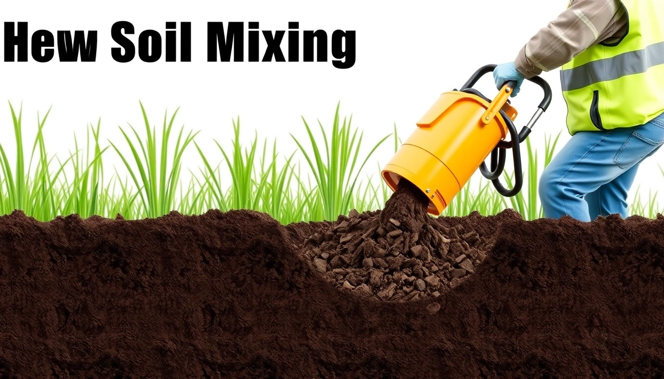
Deep soil mixing suits sites where the problem is not just a thin soft crust, but a deeper zone of clay, silt, organic soil, peat, or loose fill that cannot carry load or control settlement on its own. Especially useful when the weak soil extends below the depth where shallow excavation or replacement would be practical, often several metres down, and when you need improvement without open-cut replacement across the whole area.
You already need the basic site facts: the soil profile from a geotechnical investigation, the groundwater level, the structure or pavement loads, and the performance target. No borings log, lab results, or design basis? Then you are still at the “figure out the ground” stage, not the “choose a method” stage. Usually that first pass includes undrained shear strength, moisture content, Atterberg limits for fine-grained soils, and settlement estimates.
Not every weak-ground problem belongs here. I would not steer someone toward deep soil mixing when the real issue is a shallow bad layer that can be stripped and replaced in 1 to 2 metres, when the soil is full of boulders or demolition debris that a mixing tool cannot penetrate, or when the design needs immediate full-strength support from day one. Highly organic soils and aggressive groundwater call for extra caution, too; binder choice and durability can make or break the job.
For a high-stakes foundation or roadway, the call should sit with a geotechnical engineer and usually a contractor who has the right mixing equipment and quality-control procedures. What a reader can do first is pin down the failure mode: settlement, bearing, slope stability, or lateral spread. What should not be improvised is the binder dosage, spacing, and verification design.
What deep soil mixing actually does to the ground
Deep soil mixing turns weak soil into a soil-cement composite. A mixing auger, paddle, or cutter goes into the ground, and binder slurry or dry binder is injected while the soil is mechanically blended. The binder reacts with water and soil particles to form hardened columns or panels. Not concrete. Different animal. The result is improved ground with a new engineering behavior: higher strength, higher stiffness, lower permeability, and better resistance to deformation.
The wording matters. A “column” is a treated vertical zone, often circular in plan, that carries load or improves stability; consult the project geotechnical engineer on geometry and performance, because column size and behavior depend on the soil and binder system. A “mass mixing” or “block treatment” pattern overlaps many columns so the whole treated zone acts together; consult a geotechnical engineer before relying on that assumption. A “binder” is usually Portland cement or cement blended with slag, fly ash, or lime depending on soil chemistry and durability goals. Because clayey soil, organic soil, and saline ground react differently, the mix design is not one-size-fits-all; deep soil mixing works for weak subgrade and foundation support only when the design matches the ground conditions and verification plan. Sources: FHWA ground improvement guidance and EFFC/DFI practice documents.
The usual design outputs are target unconfined compressive strength, often checked at 7, 14, or 28 days in lab curing; stiffness improvement; and settlement reduction. A site might use isolated columns under a footing, a grid under a slab, or a treated block beneath an embankment; consult the geotechnical engineer for the layout that fits the load case. In some projects, the treated soil also acts as a seepage barrier; consult the designer because hydraulic performance depends on binder, continuity, and soil chemistry.
The common mistake is thinking the columns themselves are the whole system. They are not. Load transfer also depends on arching, the untreated soil between columns, the raft or slab above, and the interaction with groundwater and construction sequence; consult the project geotechnical engineer because the load path is site-specific. When deep soil mixing is done badly, the ground may look treated from the surface but still show weak pockets, variable strength, or excessive settlement after loading.
How is deep soil mixing installed?
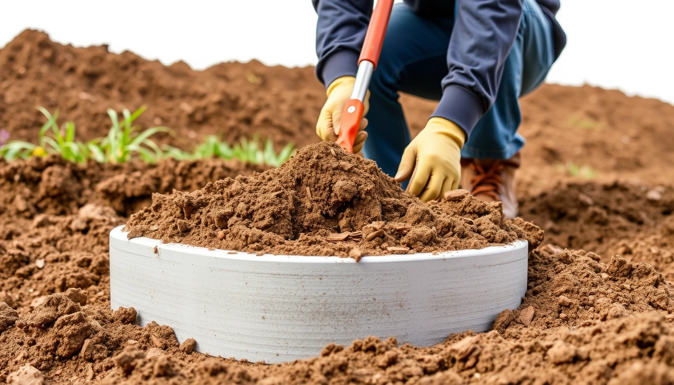
Deep soil mixing goes in by drilling the mixing tool to the design depth, blending soil and binder in overlapping passes, and checking that the treated zone reaches the intended size and strength before the structure goes on top. Wet method or dry method, the sequence stays familiar: set out the pattern, penetrate, mix, inject binder, withdraw while remixing, and confirm what was built.
- Lay out the treatment grid. Mark column centers or panel lines to the specified spacing, often on a 0.8 m to 2.5 m grid depending on the design. Check offsets against the control drawings and fixed site benchmarks. Trouble starts when tolerances drift far enough to leave untreated strips between columns.
- Check the ground and obstructions. Confirm soil profile, groundwater, and any buried utilities, boulders, rubble, or old foundations before drilling. The bore plan has to match the geotechnical log, not just the civil plan. Refusal, sudden torque spikes, or tool bounce mean the ground may contain obstructions or a harder layer than expected.
- Select the binder and dosage. Pick the cementitious mix for the soil chemistry and required strength, then set the binder rate as a design parameter rather than a guess. Check the mix plan against lab trial results and target strengths such as 500 kPa or 1 MPa if those are specified by the engineer. A problem is dosage that wanders without control, which leads to uneven column strength.
- Penetrate to full depth at the specified rate. Advance the tool to design depth at the planned rotation and penetration rate, which must stay within the equipment and soil limits. Depth is verified from rig instrumentation or marked drill string. If the tool stalls or deviates, the column geometry is no longer what the design assumed.
- Inject binder while mixing on withdrawal. Pump slurry or dry binder so it disperses through the soil while the tool is withdrawn in a controlled pattern, often with multiple mixing passes. Flow rate, pressure, rotation speed, and withdrawal speed should all be recorded continuously. A problem appears when pressure drops, the flow stops, or withdrawal is too fast, leaving streaks and unmixed lenses.
- Remix the column or panel. Make a second pass where the design calls for it, especially in stiff clays, layered soils, or where continuity matters. The tool needs to re-enter the same zone, and the torque and slurry return should stay consistent. Poor remixing leaves soft seams that later become settlement zones.
- Control overlap and continuity. If the design uses overlapping columns or panels, keep the overlap within the specified band, often 10% to 30% of diameter, so no weak gap remains. As-built spacing is checked with survey points and rig logs. The headache is a neat-looking pattern with hidden gaps that break the load path.
- Cure before loading. Protect the treated ground from early excavation, vibration, or fill placement until the binder has gained enough strength, typically checked at 7-day and 28-day samples or project-specific criteria. Strength is verified by coring, wet grab samples, or load tests where specified. If the ground sloughs, mud boils, or deforms during early loading, it was loaded too soon.
Depth and dose are the two field numbers that matter most. Depth tells you whether the weak layer is fully treated. Dose tells you whether there is enough binder to build a meaningful matrix. If either one drifts, the result is not just a little worse; it can be a different ground condition entirely.
What should you check before you commit to this method?
Before you commit to deep soil mixing, check the soil type, groundwater, load tolerance, access, and verification plan. That five-part check tells you whether the method is technically sound or merely attractive because it avoids excavation.
Start with the soil. Deep soil mixing is strongest in fine-grained soils, soft clays, silts, and some organic soils. In loose clean sand, the improvement mechanism is different and often less efficient unless the design specifically addresses liquefaction or seepage. Very organic peat can be a bear; binder demand may rise and long-term strength gain can disappoint because the organics interfere with cement hydration.
Then look at groundwater and chemistry. Sulfates, chlorides, low pH, and high organic content can change binder performance and durability. That is why trial mixes and lab curing matter. A binder that performs well in one clay may underperform in another. Honestly, I would want mix designs based on site-specific testing, not a default recipe.
Access matters more than many people expect. Deep soil mixing rigs are tall, heavy, and need room to position, rotate, and move. Tight urban sites, bridge approaches, and working docks can be suitable, but only if the rig can physically operate and the spoil or slurry can be handled without contaminating the work area. If a project cannot tolerate mud handling or vibration, it may need a different approach.
Finally, check how success will be measured. If nobody plans to verify unconfined compressive strength, treated column diameter, continuity, and settlement response, the project is flying blind. Good verification usually combines construction logs, sampling, and one or more field performance checks. Without that, a “treated” ground mass can still hide weak bands or underdosed areas.
A generic article often leaves out the economics of certainty. Deep soil mixing is not cheap compared with doing nothing, but against over-excavation or deep pile foundations it can be the more practical option when settlement control is the real target. The cost question should be tied to risk reduction, not just unit price.
When should you stop and choose another approach?
Stop when the soil, access, or performance target makes soil-cement improvement the wrong tool. Deep soil mixing is not a cure-all, and pushing it onto the wrong site usually buys expensive uncertainty.
Large boulders, demolition debris, or old timber foundations: these can block the tool or leave untreated voids — switch to excavation, removal, or a foundation system that tolerates obstructions.
Very shallow weak soil, usually the upper 1 to 2 metres: the problem is too close to the surface for deep treatment to be efficient — strip and replace, use geogrid-reinforced fill, or redesign the footing.
Need for immediate full structural capacity: soil-cement gains strength over days and weeks, not minutes — use driven piles, drilled shafts, or staged loading if the schedule cannot wait for curing.
Highly organic peat with extreme variability: binder demand may become unpredictable and strength gain uneven — expect trial sections, or consider removal and replacement where feasible.
Ground conditions that are too hard or too dense for the rig to penetrate: the tool may refuse or wander — choose drilling, piling, or another ground improvement technique.
Environmental limits on spoil, slurry, or binder chemistry: some sites cannot accept the disturbance or the material handling — use a drier or less disruptive method, or change the foundation concept.
Ignoring those stop signs does not usually cause a small performance drop. It produces a treated zone that looks acceptable from the surface but fails to meet settlement or stability targets when loaded.
The mistakes people actually make, and what they cost
The most common mistake is treating all weak soil as if it behaves the same. It does not. A clay with modest natural moisture behaves differently from peat, and a silty layer above a clay seam can change how the binder spreads. The result is either an underdesigned mix or an overdesigned one. The correct alternative is soil-specific trial mixing.
Another mistake is focusing on column spacing while ignoring overlap and continuity. A neat grid can still leave weak strips if the diameter is smaller than assumed or the tool wanders. The consequence is differential settlement between treated zones. The right alternative is to verify as-built diameter and keep the survey tied to the actual rig logs.
A third mistake is over-relying on the binder rate alone. More cement does not automatically fix poor mixing, bad timing, or a wrong withdrawal rate. The consequence is clods of overtreated soil surrounded by weak soil. The correct alternative is to control rotation, penetration, withdrawal, and flow together.
A fourth mistake is loading the ground too soon. Soil-cement needs cure time, and early fill placement or construction traffic can crush the partly hardened matrix. The consequence is loss of strength before the structure is even complete. The proper alternative is staged loading and documented cure checks.
A fifth mistake is skipping verification because the treated area “looks fine.” Deep soil mixing can hide defects below grade. The consequence is discovering the problem only after settlement starts. The better alternative is sampling, coring, or performance testing before accepting the work.
These are not academic errors. They are the reasons a project that should have given 20 years of service starts showing movement in the first season.
How do you know the treatment worked?
You know the treatment worked when the treated ground meets the project’s strength, stiffness, and settlement targets under the intended loading condition. That is not judged by appearance alone. It is judged by a combination of construction records, sample strength, and field response.
The usual checks include fresh and cured sample testing, such as unconfined compressive strength at 7 and 28 days, plus inspection of drilling logs for depth, penetration rate, rotation, and binder flow. Some projects also use coring to inspect continuity or plate load testing to see how the improved ground behaves under pressure. For settlement-sensitive work, instrumented fills or settlement plates can show whether the ground is moving within the allowed range.
A good result is not “hard like concrete.” It is “predictable enough for the structure.” That distinction matters because deep soil mixed ground still behaves like an improved soil mass, not a reinforced slab. If the project demands exact pile-cap behavior, this method may be the wrong tool.
I would call the work suspect if the logs show irregular depth, the binder consumption drifts, samples vary wildly, or the treated area settles more than the design allowed during staged loading. In those cases, the right answer is to stop, review the data, and have the geotechnical engineer decide whether remediation, additional treatment, or a different foundation system is needed.